62 minutes reading posted in Bachelorthesis Security Coreboot
with tags: coreboot security
Securing Hardware with Coreboot
This document provides an overview about current state of security in the field of hardware firmware and try to address some of the issues with an open source solution called ’Coreboot’. With this thesis further issues of modern hardware will be explain.
Table of Contents
- Securing Hardware with Coreboot
Introduction
A laptop is sent in for an audit. It was reported that this particular laptop was exhibiting some ‘odd’ behavior. ‘Odd behavior?’ one might think. Just a user who is doing it wrong. Minutes later, an Operating System (OS) with a famous logo has been booted and the investigation begins.
The misbehavior is that at any given time on a website an advertisement is displayed. Imagine a blank HTML page with the imprint of ‘Hello World’ and right beneath it a width banner for whatever sells best in this moment. ‘Odd’, one might think. The banner cannot be found in the actual source code. But a solution is at hand: The installation of an Anti-Virus (AV) software.
One AV-Scan later, a nasty malware, an abbreviation for malicious software, is found. Software that appends to any given website an advertisement banner. The AV Software suggests to do what it can do best; removing the malware. It seems that the oddness has been taken care of.
The computer is left running for another day, as routine dictates. On the next day, the weirdness is about to start over: The malware has returned. Without the Anti-Virus noticing, the malware was re-installed on the Windows laptop. Another AV-Scan tells the same story. Again, the AV Software deletes the malware. Was this maybe a malfunction of the AV Software?
The malware is found again. Again a banner for some dirty websites is concatenated into the ‘Hello World’ page of the web browser. This time, another AV Software is installed. As its predecessor, it unveils the malware and erases its traces from the surface of the hard disk. Yet only, to be found once more later. One might change to another AV product of the many solutions the market offers, in the hope one of them might deal with it correctly. However, why should anyone trust a compromised system anyway? The auditor decides to do a fresh installation of the Windows laptop.
Some time later, the laptop has a new installation of Windows, including the newest security patches. The odds are now against the malware, one might think. For another night, the computer keeps running and the malware seems to be gone. But what is this? The next day, the malware returns. Did the malware just re-install itself?
A conclusion comes to mind: Has some hardware related component been infected? Parts of the computer will be replaced, the hard drive, the Network Interface Card (NIC) until only the motherboard remains. Fortunately, the ROM Chip in which the BIOS, the Basic Input and Output System, lives can be exchanged. The BIOS is responsible to initialize the hardware. A new ROM Chip was purchased over the vendor. The same procedure is conducted once more, re-installation of the OS and another day that passes. This time, no advertisement shows up. For once, no new malware installation is unveiled. It has been defeated!
Why do we trust a system?
In a plot like chapter one (introduction), we are not confronted with malware, but with a type of software that is named ‘rootkit’, or ‘bootkit’. A rootkit is a piece of software that acts maliciously and compromises a system in a way that it changes execution flow. Allowing arbitrary code to be executed and changing the behavior of the affected system to the authors biding. While the plot from chapter one was imaginary, one could only imagine how a researcher has found the ‘Mebromi rootkit’[5][6] 1.
With the rise of computers, they become ubiquitous in our environment. We entrust them everyday with more and more tasks that are crucial for our society as a whole. However, with this degree of importance, how much of the systems we are using can be considered to be trustworthy? In the plot of chapter one, it was an obvious situation.
Over the last 20 years, computer systems have become so complex that no one can handle their complexity. Software and hardware alike have grown in this intricacy likewise. While software can be reviewed, hardware cannot. Many vendors of hardware[7][8] also do not allow reviews. Systems are sold as black boxes and hardware vendors just implement them to their system. These are many areas in which a rootkit can nest.
Different researches[15][62][96][97] have shown that attacks on firmware components are quite likely. Some time ago, a researcher presented an obnoxious type of rootkit named: ‘badBIOS’[9]. A rootkit that is supposed to infect a system using ultrasonic sound. While many experts[10] remain doubtful about it, researchers from the Fraunhofer Institute have shown in their paper: ‘On Covert Acoustical Mesh Networks In Air’[11] that using ultrasonic sound is a valid communications channel. The security researcher Robert Graham analyzed the composed feature of the ‘badBIOS’ and concluded[12] that it is plausible.
With the development of a proof of concept (POC) rootkit ‘LightEater’[15], Corey Kallenberg and Xeno Kovah demonstrated how plausible rootkits in BIOS[16] are. ‘LightEater’ allowed the extracting of GPG keys, even when a secure OS like Tails was running.
Backdoor-Capabilities in Hardware
It is possible that a computer with all security patches still might be compromised, with changes[[13][14] deep inside the hardware, beyond detection from any software. This might be possible when it is embedded into the firmware[17][18] or in the hardware itself. Firmware is hardware specific software. The word firmware is composed out of the words ‘firm’ and ‘software’.
With the NICSSH[19 page 4], an attack was demonstrated that aims at functions in modern NICs. This attack allows to execute a minimal SSH Server within the NIC. This way, an attacker can access the hardware via the network traffic. He can then snoop all of the network traffic. While the NIC might not hold enough resources for longer traffic dumps, another device can be utilized to bypass this obstacle. Hardware, such as the graphic card, will be used in order to store the network traffic in the memory of the GPU. The CPU is almost entirely uninvolved.
Apart from potential backdoors, Intel itself does provide backdoor type capabilities within its shipped hardware. The ‘Intel Anti-Theft Technology’[20] allows to control modern processors remotely, even when the OS is turned off. It might be disabled, but even a corporation like Intel is not always capable of securing their products appropriately.
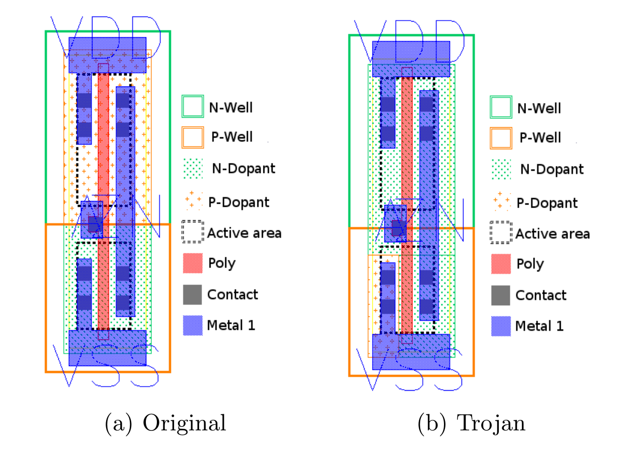
Once hardware itself becomes compromised, it is almost impossible to detect the compromised component. Figure 1.1 shows a hardware Trojan altering the behavior of logic gates that are composed out of CMOS. On the left side of figure 1.1, there is the supposed inverter and on the right side a compromised one. The compromised gate will be placed within critical components, components like a Random Number Generator (RND). This would lead to the result that the RND produces numbers of predictable manner for an attacker.[13 Page 10]
Other methods to compromise hardware exist: the Hardware Description Language (HDL)[21 page 42], for example, responsible for the designs of specific components. Another option could be the implementation of shadowing components[22] during the development process of hardware.
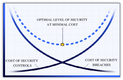
At the end of the day, this comes down to one essential aspect: The costs of time and money. The main question shows the value one tries to protect and how much would it cost to undermine this. In figure 1.2 [23], we need to look for the right spot to address security, else we will not have a reasonable degree of security. But the question that needs to be raised is, what do we want to protect? What is our asset? 2
Modelling a Threat
To find flaws, we will need to create a model of the asset we consider worth protecting. To rephrase the situation from chapter one: How could the laptop have been protected? A useful instrument to make sense of risks for an asset is the usage of a Threat Model.
Threat Model
A Threat Model(TM) is an abstract representation of systems to find flaws. Adam Shostack has developed a general approach to TMs at Microsoft:
Everyone threat models. Many people do it out of frustration in line at the airport, sneaking out of the house or into a bar. At the airport, you might idly consider how to sneak something through security, even if you have no intent to do so. Sneaking in or out of someplace, you worry about who might catch you. When you speed down the highway, you work with an implicit threat model where the main threat is the police, who you probably think are lurking behind a billboard or overpass. Threats of road obstructions, deer, or rain might play into your model as well. When you threat model, you usually use two types of models. There’s a model of what you’re building, and there’s a model of the threats (what can go wrong). [...] (Adam Shostack[3] page 24)
A TM can thus be summarized as follows: ‘whatever can go wrong’. This question is important to any devised system. How does it handle failure, misbehavior or maliciously formatted inputs. Because this is a model, we will illustrate our system in the most simple fashion. In our model, we will take a look at our current system and try to think about potentials threats, aspects that can go wrong. Once we have all reasonable possibilities, we advance the model. Extending the model with more details that were considered as a threat before. One characteristic of TM needs considering:
You’re never done threat modeling. (Adam Shostack [3] page 403)
It is important to set boundaries to a TM or else it will never be finished. Therefore, we will set the scope of our TM to aspects that are in our control. We are going to do the same as Adam Shostack has explained, but instead of thinking what might be lurking behind a billboard, we will devise a simple model that will represent a laptop to allow us to unveil potential flaws within our system. The approach for this is the following:
$$\textrm{Modelling} \rightarrow \textrm{Identify potential attack surfaces} \rightarrow \textrm{Research about Threats} \rightarrow \textrm{Revise Model}$$
Model of a Laptop
We will start with a simple mode for the TM that relies on aspects of the described problem from chapter one. We had a laptop that consisted of an OS and running a web browser. The OS was re-installed and at some point, the hardware was considered a problem. For this TM, we will use a layered model approach:
We will elucidate the TM first. Our TM consists of three areas to begin with:
- Web browser
- Operation system
- Hardware
Since users nowadays only rely on a web browser to do their work, we will focus on web browser. The level of security has changed drastically in the recent years for web browser, as research[24] has shown. Most things happen in the web or ’cloud’3. Web browsers are fast moving environments, with a lot of focus. Their code is open source, well matured and many audits were performed on it.
Projects like Firefox[25] or Chromium[26] are not free from flaws. One partially interesting contest is the ’Pwn2Own’, hosted by the Zero Day Initiative (ZDI)[27], the security team of HP. ’Pwn2Own’ is an abbreviation for ’Powning to Own’, where the word ’Powning ’is an expression used in the Hacker community for successfully gained privileges (like root or Administrator) on a system. The goal of a participant in this event is to take control of a fully patched device. ZDI provides varying laptops with distinct OSs, each running separate web browsers. When a participant can gain higher access through code execution on a laptop, hence win the devices and money. This year’s winner was Richard Zhu[29]:
He used an out-of-bounds (OOB) write in the browser followed by an integer overflow in the Windows kernel.[..] (Dustin Childs [28])
The attack aimed at a misbehavior[28] in the memory management of Firefox. The relevant point is that the attacker has gained more privileges on a system by utilizing an integer underflow within the OS kernel. Once something goes wrong inside of the kernel, it eventually leads the code to being executed with the highest permission. Flaws like this are, once found, fixed quickly by both browser vendors and OS vendors. However, this needs to be considered in the TM as well.
Why does this matter? Simply put: Imagine browsing a website and clicking on a link. This act would allow an attacker to execute code. This code would exploit the OS kernel to gain higher privileges. At this point, the attacker could do anything with the device.
An example[30] of such an attack can be seen when looking at the case of Ahmed Mansoor, a lawyer for human rights in United Arab Emirates, who received an SMS with links to a website. The content of the SMS should have lead to ’secrets’ being disclosed on the website. He did not know the SMS original address and did not open those websites. Instead, he contacted Citizen Lab to analyze and tell him what would have happened if he had open the link:
Had he done so, Citizen Lab says, his iPhone 6 would have been “jailbroken”, meaning unauthorised software could have been installed.
’Once infected, Mansoor’s phone would have become a digital spy in his pocket, capable of employing his iPhone’s camera and microphone to snoop on activity in the vicinity of the device, recording his WhatsApp and Viber calls, logging messages sent in mobile chat apps, and tracking his movements,’ said Citizen Lab [..] (BBC[30])
This means, this is not just a hypothetical thought; high profile targets are already being attacked4. This represents an extreme example, but how much could a common laptop be affected by flaws?
In 2015, media attention focused on the laptops of Lenovo. CVE-2015-2077 was unleashed and revealed that all their laptops shipped with a ’backdoor’ by default. The backdoor was a default SSL Certificate that allows to intercept all traffic, hence any type of security mechanism implemented by vendors of OS and web browsers became invalid. This flaw was called ’Superfish’[31].
How was it possible that a vendor could ship such a component on laptops? The Original Equipment Manufacturer (OEM) or the vendors of motherboards, control what is on the hardware before it is shipped to any client. OEM are the producers of hardware. They produce the hardware we are using and composing them of different components. Therefor it is their design what softwares is runs on the laptop. This includes the OS.
However, similar to the ’Superfish’ problem, other problems have been reported. Even worse, laptops were ’bricked’[32] by the OS because vendors had shipped faulty firmware.
Enhance of the TM
We have seen and identified potential attack surfaces. But OS consists of tools and components that could be compromised as the ’Superfish’ flaws have shown. At this point, we need to consider that the OS is not just a simple layer, but a system composed of different layers. The OS kernel was attacked by Zed to gain further access. This aspect needs to be addressed in the TM.
The kernel of an OS, like all other tools one needs to run an application, have undergone massive changes in the last decade. While not all of them are open, the defense mechanisms that are implemented are impressive. With the release of Windows 10, Microsoft had reworked the kernel and took an effort to increase security[33].
A kernel and/or OS can be ’hardened’[34][35], meaning to reduce its surface against attacks or increase the resilience of a system to withstand potential flaws. Many of the flaws demonstrated in the ZDI event might have been mitigated with a hardened OS and kernel. This raises another concern: How is security hardware before any OS is started and what does the computer do when it is starting? Participially with the knowledge that vendors, who are in control of the software that is shipped to customers, are building in backdoors.
UEFI
We are going to debate hardware related technologies. Vendors changed the default firmware from BIOS to UEFI. It is the default technology for modern hardware and will be required by Windows 10. UEFI[36] is an acronym for Unified Embedded Firmware Interface. It is the successor to BIOS and a deviate from EFI. Most modern devices will be shipped with UEFI by default.
History
The BIOS standard is limited in its capability to utilize modern processor features. With the development of the Itanium processor, Intel had to devise a solution to address this shortcoming. The initial proposal was called ’Intel Boot Initiative’. To reflect the effort more objectively, it was renamed[38, Page 11] to Embedded Firmware Interface (EFI)[36]. It is intended to permit an OS to interact with the underlying firmware of the hardware, as displayed in figure 2.2. We are going to intertwine this model with the Threat Model from figure 2.1 later.
EFI provides an environment to execute high-level languages like C[38, Page 11], instead of native assembler. A modularized concept was introduced to allow extending. EFI is able to handle 32 Bit and/or 64 Bit Instructions and can therefore address all of its memory.
Due to lack of compatibility with existing x86 processors and the fact that the Itanium processors were only obtainable for server systems, they did not succeed[39, page 2] on the market. With AMD’s release of a 64-Bit x86 processor, that respected the compatibility to existing x86 applications, the x86 did remain the predominant processor architecture on the market.
Intel tried to push EFI as a standard to replace BIOS on the classic x86 market, but ceased the development of it in favor of UEFI. EFI remains in the ownership of Intel, but many aspects of the EFI Standards are adapted by UEFI. EFI was designed for the Itanium processor only but altered later to other processor architecture as well. The UEFI Forum[36] adapted the EFI and developed it further[38, page30].
BIOS
Before we take a look into the UEFI architecture in-depth, we will make an introspective to the BIOS and how it boots a system. While UEFI has become the default firmware on modern computers, it has actually not replaced BIOS. Instead, BIOS became a legacy system of UEFI. This way, UEFI ensures compatibility with OSs like MSDOS.
The notion ’BIOS’ was defined by Gary Kildall in 1975[40]. His idea was quite simple: Having a pieces of firmware that initializes the hardware. Once all hardware is initialized, the firmware ceases and an OS takes over. Gary Kildall devised this for his development of the CP/MOS, later also known as ’DOS BIOs’ or ’IBMBIO.COM’. With DOS taking the lead in the market, latter expression was more established. The first version of a BIOS had no graphical interface. Only in case of an error, some type of informative message was shown, sometimes with an error noise.
In the 1990s, a need for visual surfaces was addressed for the first time. BIOS Software was extended with a GUI to allow consumers to change configurations. After some time, more features were ’added’ to the BIOS. However, this only showed downsides of it. BIOS cannot be extended. It has strong limitations: BIOS can only address up to 1 MB of memory or storage due to the fixation to the ’Real Mode’ of a processor.
Operating Modes
The ’Real Mode’ mentioned earlier in the chapter requires some explanation. Processors have different ’Operating Modes’[43, page 11]. These ’Operating Modes’ are states in which the processor acts with different capabilities. These modes are historically grown. With each generation of processors, new feature sets were added. To ensure backwards compatibility, the feature sets were packed with the different modes, so that older software would remain working with a previously introduced set of capabilities.
As a researcher[41] has shown in his work, it is possible to run software developed forty years ago on modern processors. Windows has disabled the 16-Bit subsystem with the release of 64-Bit based Windows OSes[42]. However, the processors remain capable of doing so. A program that can set the right CPU flags can again be run within the 16-Bit mode of the CPU.
-
Real Mode
-
Protected Mode
-
Virtual-8086 Mode
-
System Management Mode
-
Long Mode
Real Mode
The ’Real Mode’[43] resembles the primitive state of an Intel 8088 processor. This mode can only address up to 1MB of memory and storage. BIOS is limited to this mode because it was developed for the processor with this feature at that time.
Protected Mode
Newer models of Intel’s processors were extended with a ’Protected Mode’. With the expansion of features ,the processors became more powerful and were able to address more than 1MB of memory. Not all programs were able to handle this bigger address space. Within the ’Protected Mode’, the memory was segregated into segments.
Virtual-8086 Mode
With the usage of the ’Protected Mode’, another problem was arising, the need for programs to run within a ’Real Mode’ environment, particularly within a DOS program. For this, Intel introduced the ’Virtual-8086 Mode’, which allows a program to execute as if it was running in ’Real Mode’. This allows once more backwards compatibility.
System Management Mode
The SMM (System Management Mode) is used in different ways. Its purpose is to control hardware related subsystems e.g power management. It varies in the fact that it is not a normal operating mode as the mode introduced before. It owns many privileges which makes this subsystem interesting for an attacker. SMM can access memory beyond the control of an OS and modify memory without its consensus. Even OS like OpenBSD with specific hardening can be subverted.[50]
Long Mode
This mode was introduced by AMD[43] to allow the usage of 64-Bit addressing and instructions, whereas Intel was attempting to restart the process architectures with the Intanium Platform, which failed. AMD just extended the instruction set of the x86 processor.
Boot process
When a processor is powered on, it is going to initialize some things that are integrated into the silicium. For example, it will reset all the data in the registers and set them to the default values. The CPU will be set up in the ’Real Mode’.
Once the processor is finished with the initializing phase, it is going to load instructions from storages. This first loadable instruction is located in the ’Reset Vector’[44, page 113]. Basically, the ’Reset Vector’ is a pointer or memory address in which the processor can check for further instructions. In most cases, a simple jmp instruction is located here that will point to some address within the storage.
A code block from an original BIOS can be seen in code listing 2.1. One should notice that at this stage of the boot process it is only possible to execute assembler code; because the processor was rested or powered we deal with a ’cold boot’. This means we do not have any hardware configured like the main memory. Hence, paradigms like a Stack or Heap are not in place yet.
F000:FFF0 jmp far ptr bootblock_start
.........
F000:FFAA bootblock_start:
FF00:FFAA   jmp exec_jmp_table
.........
F000:A040 exec_jmp_table:
F000:A040 _CPU_early_init
F000:A043 ;-----------------------------------------------------
F000:A043
F000:A043 _j2:
F000:A043  jmp _goto_j3
.........
......... ; Other jump table entries
.........
F000:A08B _j26:
F000:A08B  jmp setup+stack
F000:A08E ;-----------------------------------------------------
F000:A08E _j27:
F000:A08E  call near ptr copy_decomp_block
F000:A091  call sub_F000_A440
F000:A094  call sub_F000_A273
F000:A097  call sub_F000_A2EE
F000:A09A  retn
In this code block we have a good example of a limitation. The first line is the Reset Vector, that leads to the execution of code of the ’bootblock’. The bootblock is the first code from the BIOS in which the processor sets up some basic. The code also includes the last function in the line: copy_decomp_block. This block will decompress the code.
Why does it need to decompress anything? Simple, the ’Real Mode’ is limited to one MB of space, but BIOS has grown with time. To program more effectively, the developer of BIOS came along with some ’hacks’. For instance, they implemented some of the registers of a processor with a Stack, allowing to make function calls in assembler. Another one of these ’hacks’ was the usage of the ’Unreal Mode’[45][46]. This mode allows to use up to 4GB of memory while reaming with the 16 Bit instruction set. These ’hacks’ should constitute the limitation of the BIOS and why there is a benefit of using UEFI.
mØ This will lead to the POST process, the ’power-on self-test’ in which all hardware that was found would be initialized. Some peripherals like NICs or the Embedded Controller (EC) need to load an OptionROM. Once this phase is done, BIOS will load the Boot loader of an OS.
Boot Loader
Once the hardware is initialized by BIOS, control will case to the next stage to invoke a ’bootloader. The boot loader has to setup the processor to allow the OS kernel to be loaded with long mode. At this point, we can see differences between UEFI and BIOS. In case a failure happens, UEFI can fall back to a shell and lead the user to resolve the problem. Therefore, having a boot loader within the ROM seems useful.
UEFI Architecture
The architecture of UEFI is formed out of a complex multistage boot process[38, page 249]. The image5 in figure 2.4 represents this process. The first row in figure 2.4, the row on the left side, is called ’SEC’ stage.
’SEC’ stands for Security. This stage belongs to the pre-EFI (PEI) phase and in this stage the platform specific code begins to execute. In short the system firmware will be initialized. Also, the registers of the processor will be configured as RAM. This act is named ’Cache as Ram’(CAR)[44, page 108] and is necessary to allow high-level language like C to be executed without initialized memory.
Once the SEC stage is finished, a dispatcher will be called that invokes the PEI phase. This stage can be seen on the second row from left in figure 2.4. The main memory will be initialized. Subsequently, the content of the CAR will be moved to the main memory. After the PEI stage is finished, another dispatcher will be invoked that leads to the transition into the Driver Execution Environment (DXE), seen in figure 2.4 in the third row from the left.
Within the DXE phase, a high-level code can be executed independent of the underlying platform. It sets up the code for SMM and when enabled, secure boot will be enforced. At this stage, features can be accessed. Hardware like the PCI Bus and OptionROM will be loaded. At this stage, most of the hardware should be accessible, including the network card and the EFI shell.
Once the DXE[49] phase is finished, UEFI will transit to the Boot Device Selection (BDS), as shown in the fourth row in the graph 2.4 from the left side. The BDS is a file from the DXE encapsulated. It will call an exit function of the DXE and remove every code besides the UEFI run time environment. At this point, the actual signature of the firmware is validated. Once done, it will call the boot loader from the OS and move to the Transient System Load (TSL).
In chapter Secure Boot, we will take a look at the ’Secure Boot’. The Unified EFI Forum releases an open source implementation called ’tianocore’[76]. It is the reference implementation of the UEFI standard.
Secure Boot
The core feature of UEFI is ’Secure Boot’ (SE). SE allows the usage of a cryptographic signature to verify underlying components, like the firmware. The signature will be checked against a Public Key Infrastructure (PKI).
As part of the PKI, a Platform Key (PK) will be generated. The PK acts as the root of trust. OEMs will be in control of the PK. Additionally, all keys that will be used later are validated against the PK.
Another set of keys will be generated, the ’Key Exchange Key’ (KEK). This set of keys will be used to validate the signature database (db) or the revoke signature database (dbx).
The KEKs will be validated from the PK. The KEK protects the db/dbx from alteration. The db contains a list of signatures of programs (DXE driver and apps) that are allowed to be executed.
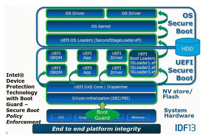
There is a difference between ’Secure Boot’ provided by UEFI and Windows’ ’Secure Boot’[52]. Windows’ relies on the UEFI one. Because of this decency, Microsoft has developed guidelines to ensure that Windows Secure Boot works with the UEFI Secure Boot. As can be seen in figure 2.5, the underlying layer validates the upper one.
Flaws in UEFI and Secure Boot
Because UEFI is responsible for the first instruction that is being executed, we will need to ensure that this is secure. Yet, UEFI is full of flaws. For once UEFI is backwards compatible, this implies that a user can use a ’legacy modus’[96]. This legacy modus is similar to the classic BIOS. This is necessary to ensure compatibilities to old OSs like DOS. But instead of replacing BIOS, UEFI extends BIOS with a more complex solution.
Further issues are that UEFI does not implement[51] any type of security mechanism like Address Space Layout Randomization (ASLR) or setting a NX bit for the memory. Each code that will be executed has the high privilege on predictable positions within memory. While Intel provides papers on how to implement UEFI securely, many vendors do not seem to care.
While there is an open source implementation (as can be read in chapter UEFI) of the UEFI standard, fixes within this implementation are not pushed directly to the OEMs, except Apple. As shown in figure 2.7, an update from the CPU vendor to the OEM needs to pass the Institute for Business Value (IBVs), the Original Design Manufacturer (ODM), and then eventually the OEM. This leads to the problem that fixes within the original UEFI code of ’tianocore’ might never reach the end-user. Even when updates occur, the end-users would have to update the software on their own.6
In the end, UEFI introduces a huge complexity with its standard, even hardware vendors have problems complying to. While the design might be fine, most of the flaws lie in implementation. Furthermore, many vulnerabilities have been existing for years within the reference implementation of the UEFI without being addressed. Vendors tend to not go along with recommendations in regards to security from Intel. UEFI forces them to take a trade-off between being secure or fast booting and the vendors tend to take latter one[96].
Thought needs been given to the UEFI Secure Boot, considering that every vendor implements it in their own matter, not always complied to the requirements Windows has for its Secure Boot. As attacks have shown, the SPI Flash Chip remained alterable, allowing an attacker to alter content of the SPI Flash Chip. This allowed to corrupt[48, page 65] the PK and put the UEFI into ’setup mode’. Once it is in setup mode, Secure Boot is disabled and an arbitrary driver can be installed. Aside from this issue, Microsoft has its own questionable pragmatics[53] in regards to the usage of Secure Boot.
Revised Threat Mode
Now is the time to revise the TM we created and build up on it. Before we do this, we will take a look on some aspects research has shown. We will take the model from figure 2.2 .
In figure 2.8, an improved version of the TM can be seen.
- Web browser - has layers of sandboxing in place.
- Kernel - Has been hardened against attacks.
- UEFI/BIOS - Almost no control about.
- Firmware - No control.
- Hardware - No control.
When we take a look at what type of research is out there, we will notice that as we go closer to the hardware, the fewer resources we get. Web browser, OS and Kernels have been hardened for the last decade to withstand many different types of attacks. They are universally more exposed to users and therefore being attacked more often. Special attacks were made and resilience is in place.
While flaws exist in all parts of this model, one should consider the lifetime of a flaw and how quickly they are solved. Flaws that are found in web browser are fixed within days. But more importantly, they are distributed to the users in almost the same time.[24, page 268]
Flaws in Operating Systems, can live up to 5[54] or 7[55] years. Some are fixed within days, some take half a year. It depends on the vendors. But OSes are fixing their flaws in general. Those fixes are distributed in releasable time to the users. Not every user is installing them; however, this situation has improved over the years. (Compared to Windows XP time).
Flaws in hardware persist even longer. The Meltdown/Spectre[64][65] vulnerability has remained undetected for 20 years[56] and even months after the disclosure, not all processors have been addressed. There are no processors that are not affected and it might take some years before processors are released without the flaws. Intel has an interesting way to address these flaws: They update a special firmware, called microcode[57], that mitigate the flaws on the hardware.
Similar can be said about UEFI/BIOS related firmware. Even when flaws are unveiled, this does not imply that those flaws are fixed. OS and web browsers have developed strategies to patch effetely, in contrast to hardware and firmware[96]. Also, the User is responsible for installing updates for their firmware. But how many users do so is unknown. Flaws that are found and reported to Intel might lead to a ’fix’[59]. But these flaws are not distributed to the users, but to the OEMs and it is not certain that this vendor will release/push an update to the clients.
There is very little information about firmware related issues. We can expect that flaws are not patched or at least not communicated.
Conclusion
The main goal of a Threat Model is to find flaws within our asset. While we could keep Threat Modeling, we will stop to model now. To keep in reasonable costs(see figure 1.1)7. But how can we address found flaws? Considering the current model (figure 2.9) we can only address one aspect: The UEFI/BIOS layer. The firmware underneath the UEFI/BIOS layer is mandatory for the hardware to operate, since hardware itself cannot be changed.
Matrosov[61] has suggested (figure: 2.9) that the firmware is the weakest link in the current hardware, even with features like Secure Boot.
We come back to the question of the costs. How much one is willing to spend in order to attack someone and how much one does want to invest to avoid being attacked. Luckily, we can replace the obnoxious UEFI/BIOS with a proper solution: coreboot[96].
Coreboot

Coreboot is an open source project to boot a computer. The purpose of the project is to replace the property components like BIOS/UEFI from a motherboard. Coreboot will be installed into the SPI Chip of a computer and is then responsible for initializing the hardware.
coreboot is an extended firmware platform that delivers a lightning fast and secure boot experience on modern computers and embedded systems. As an Open Source project it provides auditability and maximum control over technology. (Welcome text from coreboot.org [[4]]@coreboot)
History of coreboot
Coreboot was founded in 1999 by Ron Minnich from the ’Los Alamos National Labs’ (LANL)[ 1][102]. The project made its first appearance as ’LinuxBIOS’, thanks to the idea of replacing the BIOS with Linux. By letting Linux take over the necessary hardware initializations, Ron Minnich wanted to save time during the boot process. It is a matter of fact that the BIOS is taking a long time to set up hardware and slows down the boot process. For example, the enumeration of PCI devices on the bus is done twice, first by the BIOS and thereafter by the OS, whereas a gPXE interface needs several seconds to minutes to be initialized correctly by the BIOS.
The LANL operated clusters of about 8000 nodes and ran into many difficulties with BIOS, issue like: ’No Keyboard was found, please press F1 to continue’[102]. Think about it, having thousands of nodes and it becomes necessary to connect a keyboard to press F1 to get the systems booting. Even worse, BIOS and UEFI are difficult to extend in their functionalities. A Linux on the other hand can be extended quite easily. The situation becomes worse when exotic hardware like InfiniBand is at hand.
One side effect of the usage of Linux instead of BIOS was that the hardware operated more reliably[102]. With LinuxBIOS, the hardware was more flexible and faster than systems with the default ROM. Also, the time necessary to boot the hardware was diminished, a system could be rebooted within 3 seconds[69]. Something that is desirable in case of a system failing in the cluster that needs to be reset.
Over the years, the project moved away from the initial concept of installing Linux onto the ROM. They moved to the approach to boot the hardware only. In 2008, LinuxBios was renamed to Coreboot, for reasons like marketing and preventing confusion[58].
Architecture of coreboot
In the chapters UEFI and BIOS the boot process was explained. We will do the same with coreboot. It has only four stages:
$$\textrm{bootblock} \rightarrow \textrm{romstage} \rightarrow \textrm{ramstage} \rightarrow \textrm{payloads}$$
When Coreboot starts, it passes four stages[1, Building coreboot with Intel FSP, p. 76] before OS will be loaded. When the processor is powered on, the first instruction from the processor will execute the bootblock of coreboot.
CBFS
The Coreboot File System (CBFS)[68] is not a real File System (FS) in the classic sense. Rather than being a FS, it defines structures that are in its design related to a FS. It defines the format in which data is stored on the SPI Chip. All data is located within CBFS blocks in binary format.
One important block in the CBFS is the ’Master Header’. It is located within the bootblock. The ’Master Header’ contains vital information that is fundamental for coreboot. This information is necessary for utilities at build time to work with. It helping to calculate the physical address on a normal x86 system. This simplifies the process of find the location during runtime.
All other blocks of the CBFS define as ’Components’ blocks and are located behind the ’Master Header’. Within the Components, different data types exist, declared with a header before the data with the types of ’Stages’ and ’Payloads’. Data that consists of independent binaries will be stored in a structure called SELF (Simple ELF)[70]which is of type ’Payloads’. The ’Stages’ are loaded during the boot process and consist of a single blob of data in binary form.
bootblock
The primary purpose of the bootblock[71] stage[ 1] is to put the processor into the 32-bit protected mode and prepare the CPU to be configured as CAR[44, page 123]. The bootblock is placed at the last 20k of the SPI Chip. In Listing 3.1, the first instructions are shown. The computer will be executing the Reset Vector and point to a specify address in memory.
  .section ".reset", "ax", %progbits
  .code16
.globl  _start
_start:
  .byte  0xe9
  .int   _start16bit - ( . + 2 )
  .previous
The code will jump to the _start16bit function. Several important things are done here, for example setting up the Global Descriptor Table (GDT) and putting the processor into the 32-bit protected mode. Afterwards, the code jumps to the _start32bit function. From there, execution is continued in the chipset related romstage.
romstage
At the romstage[1, page 80], the processor performs ’execution in place’ (XIP) with assembler code, because the main memory is not available yet. The assembler code in the bootblock stage is generic, but the code in romstage stage is platform specific. The first step in this stage is to configure the processor to use CAR. Hereafter, a minimal environment for running C is set up.
Once the stack and heap are configured, the processor is able to execute simple C code. The next calls are for the initialization of the DRAM. Setup of DRAM is complex and developing this in a language like C is simpler. When the memory is configured, the existing entries in the CAR will be copied into the main memory. With this step, the romstage ends and the ramstage begins.
ramstage
At the ramstage[1, page 81], the basic functions of a system are initialized. The system has access to the main memory and can execute code. The peripherals are configured now. That means any I/O related devices will be enumerated, further application-processors and the SMM are prepared.
The ramstage uses a state machine to run the hardwaremain function. The ramstage utilizes a device tree for this. The device tree is a list of legacy and PCI devices that are connected to the system, aligned in a hierarchical structure. Each motherboard needs to configure the device tree before it can be compiled. This file is called devicetree.cb[1,page 82]. Additional devices will be appended during run time to the device tree once the state machine finds them.
When the enumeration is done, the SMM is configured. Legacy and ACPI tables are set up. Then, the SMM will be locked. This marks the end of the ramstage. Coreboot will seek for the CBFS and load the located payloads.
payload
The payload[1, page 82] stage marks the last stage of coreboot. Within this stage, none-coreboot related functions are executed. That means it will be at largely used to call an external program to start up an OS. Coreboot is able to store programs, like the Linux kernel within the SPI Chip.
Payloads are usually projects separate from coreboot. Many payloads support an integration to coreboot. The default payload of coreboot is SeaBIOS. It is possible to integrate with the cbfstools common ELF based binaries. For applications that are not supported for coreboot, the libpayload is supporting the integration process.
Possible payloads
Possible payloads are:
- SeaBIOS - A classic BIOS type interface
- UEFI via Tinocore[76]
- Linux Kernel
SeaBIOS
SeaBIOS[72][75] represents a classical 16-Bit based x86 BIOS implementation that is well adjusted to coreboot. It is able to read CBFS and other payloads. It can also load Windows by chaining different boot loaders.
Setup Coreboot
To get coreboot installed on a laptop, it needs to be build. There are not binary builds at your disposal. For this, the source code is necessary. Coreboot has a build chain that will be installed first; we only rely on i386, not all platforms need to be built. After the tool chain has been built, the configuration needs to be set. It is recommended to test the tool chain first, by building an image for qemu. Afterwards, the hardware related configuration needs to be done. To get all required aspects for the build, the image from the SPI chip needs to be extracted. Once all aspects are present, coreboot can build an image that can be written onto the SPI Chip.
At this point, we will checkout the source code from coreboot with git[77]. The latest release[73] of coreboot was used. The code was forked[78] to ensure a constant code base.
git clone https://github.com/coreboot/coreboot
git submodule update --init --checkout
make menuconfig
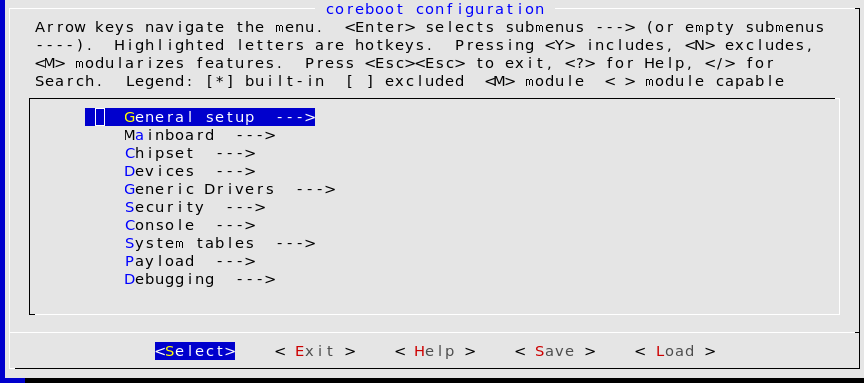
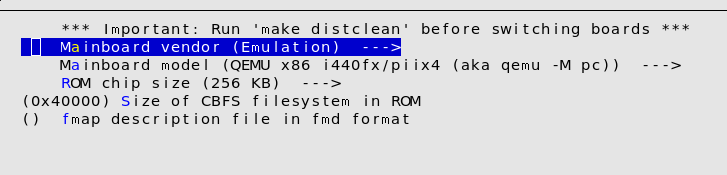
Coreboot uses the same tool to create its configuration file as the Linux kernel. By default, coreboot is configured to build an image for qemu. We can use qemu[79] to test the build chain from coreboot. No changes in the configuration are necessary to build a ROM for qemu.
make crossgcc-i386 CPUS=2
The log for the build can be seen in the appendix. Once the build is
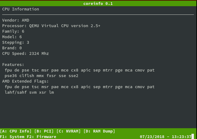
done, qemu can be used to start VM with a coreboot ROM.
qemu-system-x86_64 -bios build/coreboot.rom -serial stdio
The output can be seen in figure 3.3.
We have a working build system that can be used to make coreboot.rom files and start them. The next step is to adapt coreboot to hardware and run it on the hardware.
Issues
During the first setup of the coreboot, some problems occur that are worth mentioning.
Build environment
On an archlinux based Linux distribution, coreboot was not able to be built properly. The GCC (8.1) compiler was too new and therefore not supported. To address this issue, a virtual machine with Ubuntu (16.04 LTS) was used. The problem is known to coreboot developers and a branch exists that is trying to resolve it.
Inconsistent Documentation
The coreboot project moved its default documentation system from a media wiki into the source code directly. The documentation will be rendered with python using Sphinx. The documentation is hosted by ’Read the Docs’[73]. This leads to the problem that the main documentation is inchoate and lacks many of sites of information. On the other hand, the wiki consists of many different entries. These entries might refer to an earlier version of coreboot. Sometimes, the information found in the wiki is contradictory to the actual state.
No hardware support
![Mainboards Supported by Coreboot[74]](/pictures/supported_hardware.png)
The author intended to use a Lenovo x240. This type of device is not supported[74] by coreboot, as can been seen in figure 3.4.
Hardware
Something interesting should be taken into account when considering newer hardware like the Lenovo x240: ’Intel Bootguard’.
Intel Bootguard
When Intel realized[2, page 145] that people were abusing and modifying their firmware in a matter they did not want, they took action. Especially with the implementation of TPM and UEFI, the firmware was more an attack vector8[61][62] than ever before. This was addressed in the ’Trusted Execution Technology’.
But how can we ensure that the hardware will only operate with the correct firmware? Intel devised a solution for the problem: Each CPU has a register to hold a value. Once the value is set, it will be ’fused’ into it, making its value persistent and unchangeable. This fuse is named: ’field programmable fuses’[2,page 150]. The value will be a cryptographic RSA only the OEM has the private key for.
The OEM needs to make further adjustments to the boot process to secure the software cryptographically. Once adjustments are set, the firmware will cryptographically verify the installed firmware image. The firmware will be checked against the valued fused into the hardware. When the verification fails, the computer will not start. This feature is called: Intel Boot Guard (IBG or BG)[2, page 51].
However, Intel lets the OEM decide if they want to utilize this feature or not. The problem that follows that result from this is that coreboot cannot be installed without a valid signature of the OEM once IBG was enabled. Many devices nowadays are shipped with BG features enabled by default, denying the use of any other firmware[63, page 54].
The coreboot project provides some tools to check the state of a laptop in regards to IBG. intelmetool allows access to get the state of Bootguard.
sudo ./intelmetool -b
...

ME Capability: BootGuard                                  : ON
ME Capability: BootGuard Mode                             : Verified & Measured Boot
On a Lenovo x240, a successor to the x230 and x220, the Intel Bootguard feature is activated, denying anyone but Lenovo to run any type of firmware on it. We could see it also on the logo outside of the laptop with ’vPro’[106, chapter ’Intel Boot Guard’].
x220
Since the Lenovo x240 has Intel Bootguard enabled, another laptop was purchased to install coreboot. A Lenovo x220i will be used. The x220[66] is a device known to work well with coreboot and have full support, as can be see in figure 3.4.
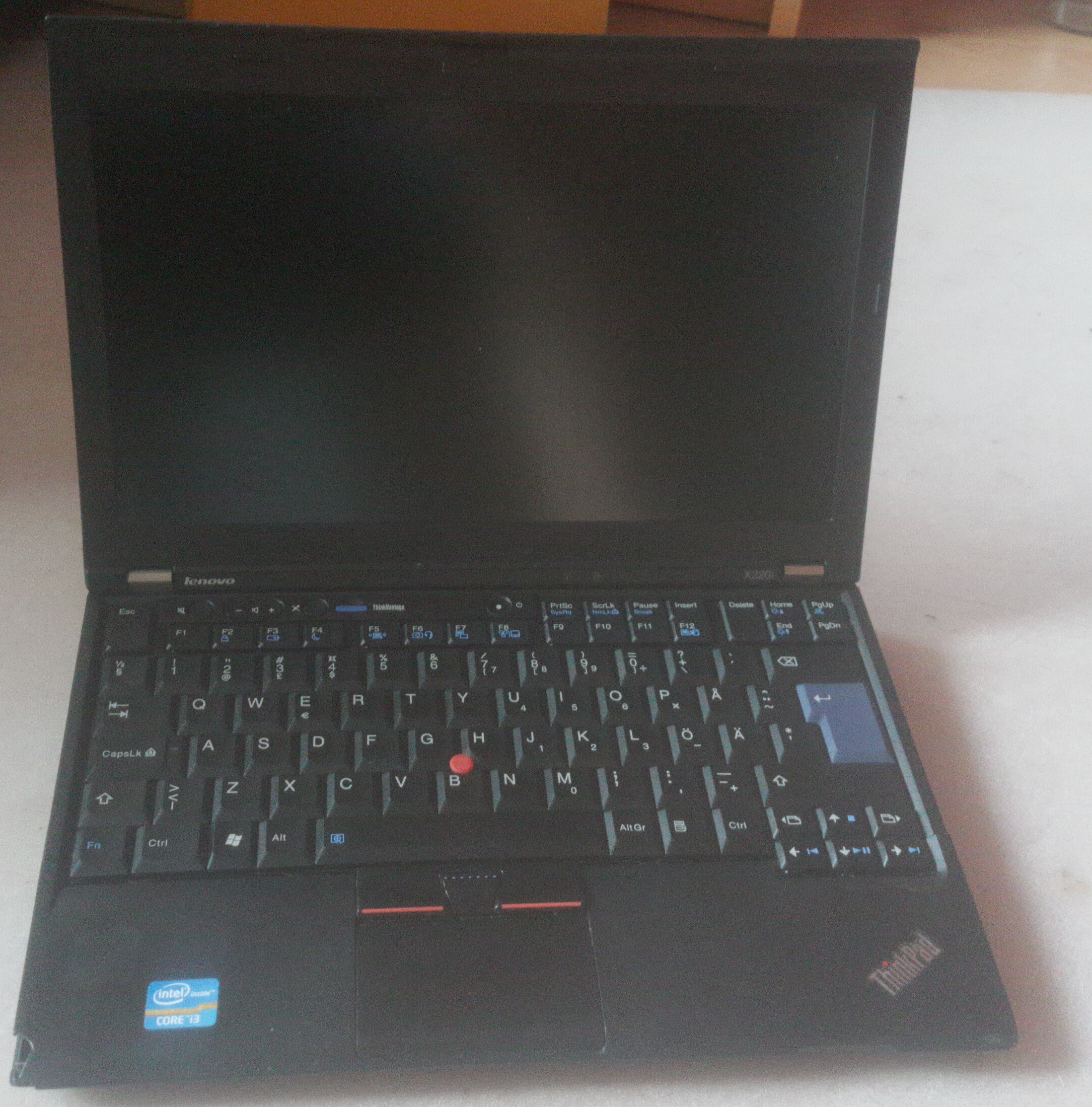
Other devices of the ’X’ series can be used, for example the x200. The x200 was certificated[67] by the FSF as free as possible with coreboot. However, the x220i will be used because it also is supported by the Heads project, otherwise a x200 would have been chosen. The x220 was installed with Ubuntu 16.04.
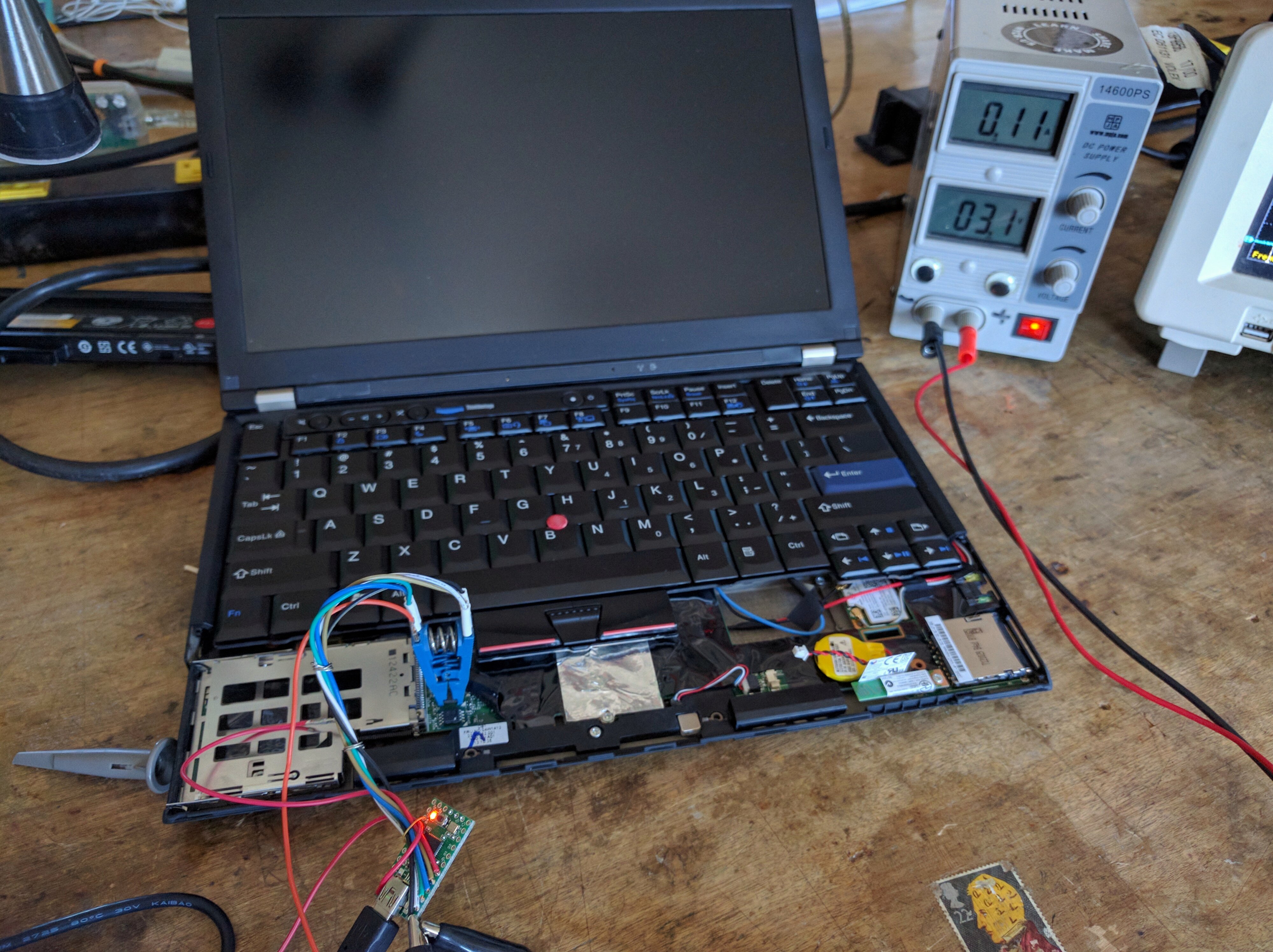
External SPI Programmer
Another precaution we need to take care of is an external SPI Programmer. For the initial installation of coreboot on a SPI Chip, an SPI Programmer is necessary. A Raspberry Pi A+ was configured to be a SPI Programmer(Seen in figure: 3.7). Because the SPI Chip on the laptop is locked down, it is not possible to alter the content during run time. It is also obligatory to extract the content of the SPI Chip.
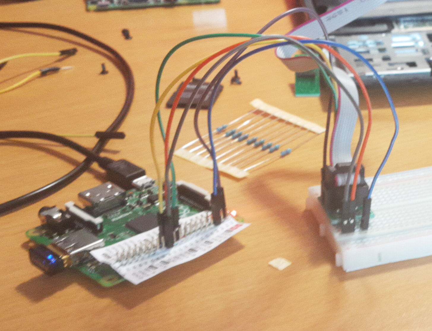
The Raspberry Pi A+ will be connected to a breadboard with the GPIO Pins. Then, a ’WINGONEER SOIC8 SOP8 Test Clip’ will be used. The clamp will be attached to the SPI Chip, without the risk that a cable becomes displaced. Before any data can be read or written, we have to test the clamp. By adding a wire between the MOSI and the MISO output of the clamp, we can validate that the SPI protocol is working as intended. The tool spidev_test[80] was used for the validation, the result is documented in listing 3.6.
root@raspberrypi:~# ./spidev_test -D /dev/spidev0.0
spi mode: 0
bits per word: 8
max speed: 500000 Hz (500 KHz)

FF FF FF FF FF FF
40 00 00 00 00 95
FF FF FF FF FF FF
FF FF FF FF FF FF
FF FF FF FF FF FF
DE AD BE EF BA AD
F0 0D
The next step is to expose the SPi Chip on the Lenovo x220i and attach the clamp.
Exposing the x220
The SPI Chips are located directly on the motherboard of the x220. Hence, it is mandatory to dismantle the x220. The SPI Chip is located beneath the touchpad, right next to the keyboard.
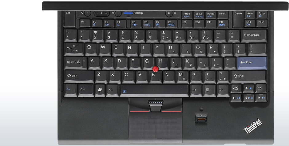
First, we need to remove the screws from the bottom.
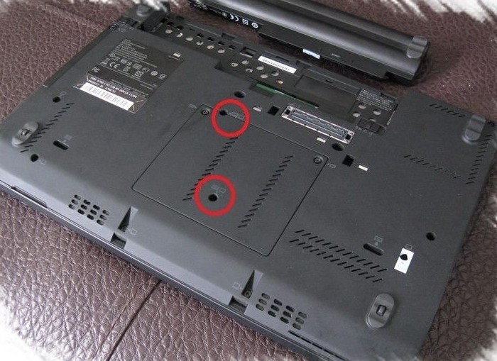
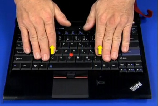
Once the screws are unscrewed, the x220i can be turned and the keyboard can be removed. By carefully pushing the keyboard up, in direction of the screen, we will slide the keyboard out of its enclosure.
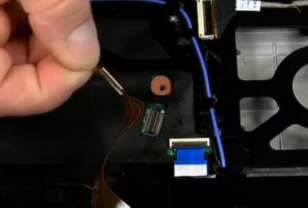
The keyboard is connected to the motherboard with a thin wire, this wire needs to be removed. This is optional.
The wire has a small plug on the end, right next to the motherboard. This can be unplugged.
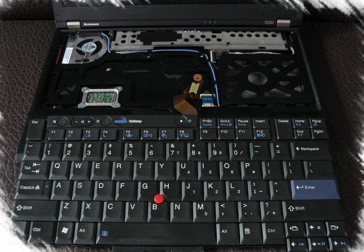
The last step is to push upwards the entry case inside of which the touchpad is embedded.
The removal of the touchpad will expose a fine plastic foil under which the motherboard sits. To access the SPI Chip, it is necessary to strip the plastic foil.
Extraction of the original firmware
With the clamp attached to the SPI Chip, it is possible to interact with the SPI Chip directly. The x220 is disconnected from any power source, also the battery is removed from the laptop. At first, some reads of the content of the SPI Chip will be performed. When the data that was read from the SPI Chip are alike, we can use the read data as backup. This allows to test the SPI Programmer for inconsistencies and produces a backup image of the original firmware to roll-back in case we have to. Another tool for this type of work is necessary:’flashrom’[80][81]. This utility is used for writing and reading an images from the SPI:
root@raspberrypi:~# flashrom -p linux_spi:dev=/dev/spidev0.0,spispeed=512 \
  -r x220.rom
flashrom p1.0-81-g0b59b0d on Linux 4.14.34+ (armv6l)
flashrom is free software, get the source code at https://flashrom.org

Using clock_gettime for delay loops (clk_id: 1, resolution: 1ns).
Found Winbond flash chip "W25Q64.V" (8192 kB, SPI) on linux_spi.
Reading flash... done.
flashrom discovers the vendor ’Winbond’[@winbond] from the SPI Chip, its size 8192 kB and the revision of the component W25Q64.V as we can see in listing 3.7. To ensure that the SPI is reading correctly it is recommended to re-read the content of SPI at least three times and then validate that the hash values of the read images are the same:
root@raspberrypi:~# ls -l *.rom
-rw-r--r-- 1 root root 8388608 Jun  7 13:29 x220_2.rom
-rw-r--r-- 1 root root 8388608 Jun  7 13:32 x220_3.rom
-rw-r--r-- 1 root root 8388608 Jun  7 13:27 x220_1.rom
root@raspberrypi:~# sha1sum *.rom
8ba448608142debd8d2e14f67794f067e8c4ae01  x220_2.rom
8ba448608142debd8d2e14f67794f067e8c4ae01  x220_3.rom
8ba448608142debd8d2e14f67794f067e8c4ae01  x220_1.rom
As we can see in listing 3.8, the SPI operates as intended.
SPI Chip Partitioning Layout
The next step is to run the ifdtool tool. ifdtool will extract the partition layout of the existing firmware. This is necessary to place the coreboot firmware correctly within the SPI Chip. For this, we need to checkout the git from coreboot and go to the folder coreboot/util/ifdtool/, run make and execute the file:
root@raspberrypi:~# ifdtool -x x220.rom
File x220.rom is 8388608 bytes
  Flash Region 0 (Flash Descriptor): 00000000 - 00000fff
  Flash Region 1 (BIOS): 00500000 - 007fffff
  Flash Region 2 (Intel ME): 00003000 - 004fffff
  Flash Region 3 (GbE): 00001000 - 00002fff
  Flash Region 4 (Platform Data): 00fff000 - 00000fff (unused)
Here, we can see the extracted partition layout of the SPI Chip.
Layout and other Firmware
![Layout ROM[60, page 15]](/pictures/rom_layout.png)
There is more firmware on the SPI Chip[60, page 15] than just the BIOS/UEFI. It also contains the firmware for the NIC (Gbe) and the Intel ME. What the Intel ME is will be discussed later.
Configuration
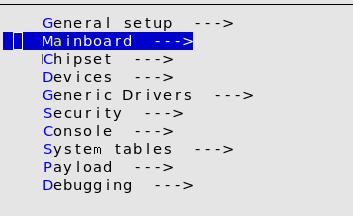
Now, we have all parts we need to build coreboot. To do this, we will return to the directory with the coreboot source code and run make menuconfig.
make menuconfig
For this, we will access the sub-menu ’Mainboard’.
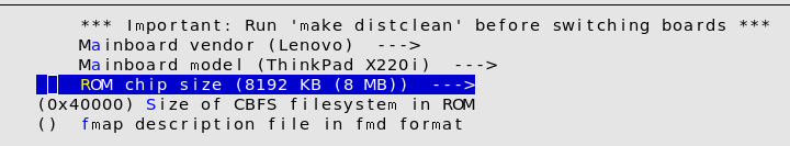
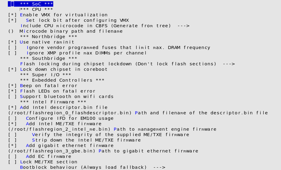
After this, we need to configure the firmware comportment we extracted in chapter Extraction of the original firmware. We need to return to the Main menu and switch to the sub menu ’Chipset’. In this sub menu, on the lower area of the menu we have a section, called ’Intel Firmware’. The extracted files need to be included in the configuration menu. Once all configurations are done, we can run make.
Installation of coreboot
A ROM file will be produced once the build has succeeded. The resulting file will be placed on the SPI Programmer, followed by the process of writing the ROM onto the SPI Chip.
root@raspberrypi:~# flashrom \
 -p linux_spi:dev=/dev/spidev0.0,spispeed=512 \
 -l ./x220.layout \
 -i bios \
 -w coreboot.rom
flashrom p1.0-81-g0b59b0d on Linux 4.14.34+ (armv6l)
flashrom is free software, get the source code at https://flashrom.org

Using region: "bios".
Using clock_gettime for delay loops (clk_id: 1, resolution: 1ns).
Found Winbond flash chip "W25Q64.V" (8192 kB, SPI) on linux_spi.
Reading old flash chip contents... done.
Erasing and writing flash chip... Erase/write done.
Verifying flash... VERIFIED.
Evaluation
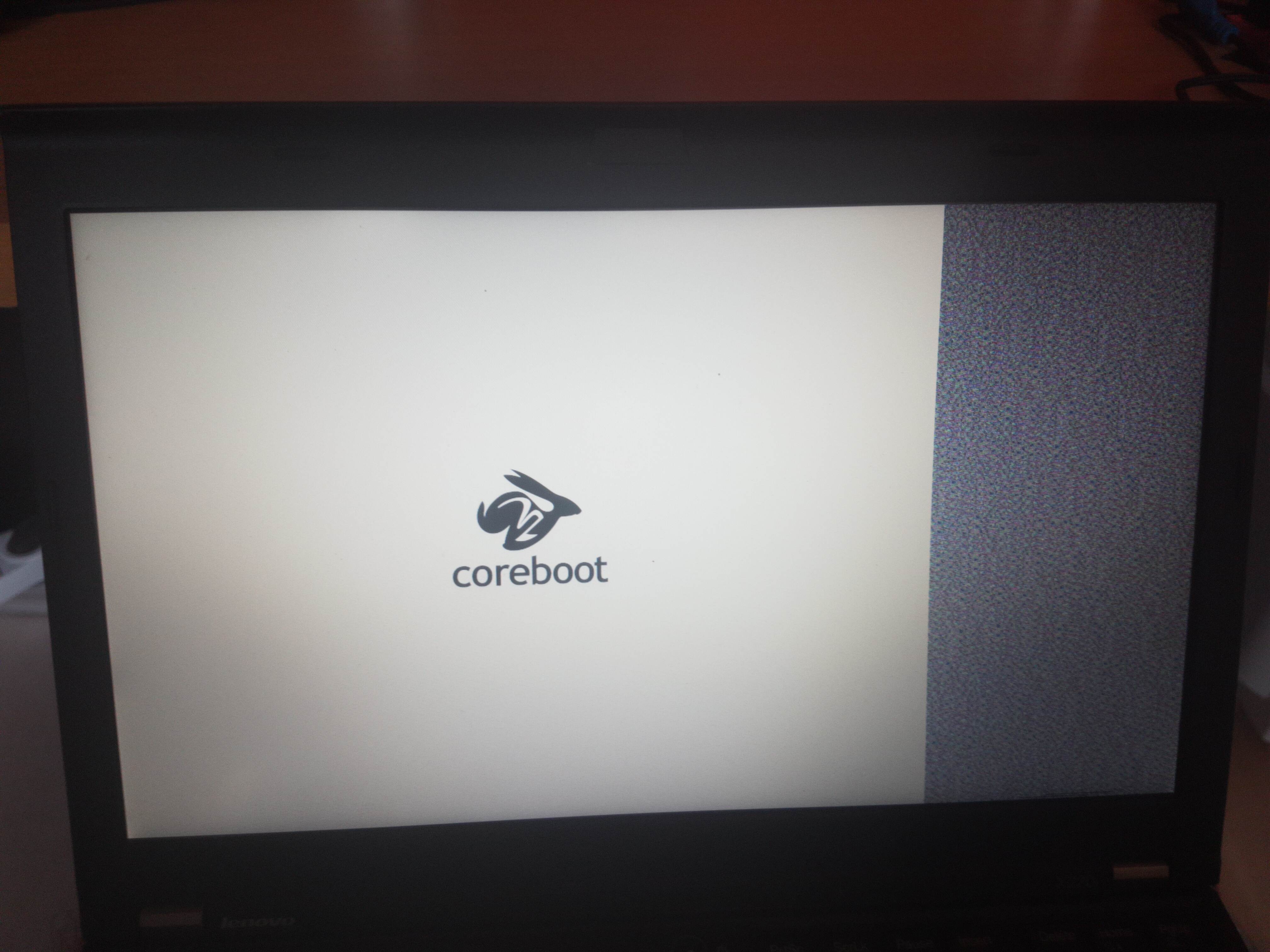
Rebooting the x220 would put the result to show. A black screen with white font is displaced, the text ’SeaBIOS’ can be read. Seconds later, Ubuntu is started. At this point, we just replaced one firmware with another. However, it did work!
Securing the Hardware
As a result of the installation of coreboot, some known[86] vulnerabilities that were affecting the original UEFI/BIOS firmware were addressed. Since coreboot is a different code base, known weaknesses of the UEFI/BIOS implementation will not affect coreboot.
-
CVE-2018-3640
-
CVE-2018-3639
-
CVE-2017-5715
-
LEN-2015-002
-
LEN-22133
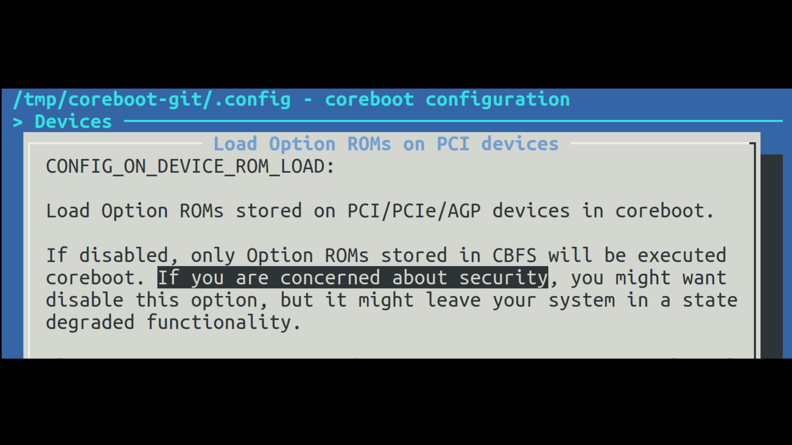
Several known weaknesses can be addressed further. Based on the findings of Trammell Hudson in his attack on Mac Book called ’Thunderstrike’[97], it can be argued that it is necessary to disable the loading of OptionROM.
On the contrary, flaws in other parts of a system like the processor itself remain vulnerable. For example the Meltdown/Spectre[64][65] flaws remain relevant. This involves that the laptop is still vulnerable to:
-
CVE-2017-5715
-
CVE-2017-5753
-
CVE-2017-5754
Conventionally, we can validate all configuration parameters of coreboot in regards to security. For instance, coreboot provides a configuration parameter for vboot[87]. vboot is a mechanism in a similar fashion to ’Secure Boot’, implemented for Google Chromebooks[1, page 99] only9.
However, Trammell Hudson explored[96] the idea of hardening coreboot before. Hudson provided a collection of tools that work on top of coreboot to secure it. Hudson enhanced the hardening of coreboot by the usage of a TPM.
Trusted Platform Module
The Trusted Platform Module (TPM)[@Ruan page 166] is a small chip or integrated circuit on a SoC that stores keys and certificates. The introduction of the TPM led to many worries about potential restrictions on hardware. Some have marked it as ’Treacherous Computing’[89][88]. It was believed that the TPM would favor certain types of executions over others, for example to implement ’Digital Rights Management’ (DRM).
The TPM turned out to be less than this. But first, we need to touch on the question: What does the ’Trusted’ imply? The word ’Trusted’ means not a binary information someone can relate to. The word rather refers to the terms of ’Trusted Computing’, allowing to make decisions at whom to trust. The expression of ’trust’ relates to a third party, allowing to make some statements about the behavior of a system. It creates a common bases to predict certain aspects in the computing, hence the name ’Predictable Computing’.
The TPM is designed this way and not to tell a user whether his hardware is to be trusted or not. The TPM is a passive device, that means it cannot alter the behavior of a system in anyway. It has no access to memory and is generally connected via the SPI or LPC Bus.
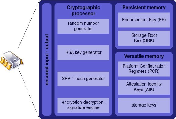
It is a simple module with a processor ranging from some MHz up to some hundred MHz. The TPM is a 28 Pin Chip or will be integrated into a SOC. There are two standards: TPM version 1.2 and 2.0. The TPM consists of a little bit of RAM and some NV RAM (see figure 4.1). In general, it has just space of several KBytes up to MBytes, depending on the vendor and price.
The TPM is able to encrypt, decrypt, and sign data cryptographically, but only small amounts of data. The hardware of a TPM is limited and the process of, for example, signing anything is very slow and might take up to 20 seconds. Within the TPM, a special register set exists, the ’Platform Configuration Register’ (PCR). The PCR is used for taking measurements. Its purpose is to measure the boot process, the results of the measurements are stored within the PCRs.
The TPM defines an ’Extend’ operation to update the value of a PCR as following[88][2, page 170]:
$$ \textrm{PCR}_{\textrm{new}} = \textrm{SHA}( \textrm{PCR}_{\textrm{old}} || \textrm{SHA}(\textrm{DATA}) )) $$
In the case of the TPMv1.2, this is a SHA1[90] and the value the PCR can hold is 20 Bytes. This ’Extend’ operation is a chaining signature. The chain consists of measurements from different boot stages, beginning with the initial measurements from the Intel ME, that makes the first measurement, followed by the next boot stage. Each stage updates the PCR with the measurement of the current stage plus the value from the previous measurement. This will include any OptionROMs until the boot loader.
The PCR therefore allows to measure the time a system needs to boot. Provided by the fact, that a change in one of the components occurs, the values of the PCRs would differ. It is possible to detect tampering or chances within the boot process. However, the TPM cannot interact in any way with the system. When the PCR values are mismatched, the TPM cannot force the system to halt.
The OS kernel needs to extract the result of the PCR and determinate that something went wrong. Nevertheless, when the kernel is compromised, it could simply fake this.
At this point, several aspects become more difficult. The TPM owns a cryptographic pair of keys (private and public), the ’Endorsement Key’ (EK). Those keys are burned into the TPM during the manufacturing process and should never leave the device. Besides the TPM, no one should have access to keys. The key can be employed in a process called ’Remote Attestation’ (RA). This can be used to let the TPM attest against a remote point. Although the EK could be used for this attestation, worries about privacy were raised. Alternatively, an ’Attestation Identity Key’ (AIK) will be used that derives from the EK.
The remote endpoint will get a certificate from the TPM. This certificate is signed by the TPM and chained with the SSL certificates from the manufacturer, allowing the remote endpoint to validate that the TPM is the one who signed the certificate. Yet, the certificates of vendors are often not maintained or renewed and will be transmitted over HTTP.10
With the AIK, the state of the PCR can be signed and transmitted to a remote endpoint, this process is called a ’Quote’. With the Quote mechanism, a remote endpoint can ensure that a system is in a specific state. Again, the mechanism relies on the remote endpoint validating this data, but it cannot tell anyone reliably whether the system was compromised or not. Furthermore, this process relies on an Internet connection.
Joanna Rutkowska[100] from the Qubes OS project took TPM in another direction. She worked out the ’Anti Evil Maiden’. The TPM is able to ’Seal’ a secret that is only decrypted again when the PCRs are in a specific state. This can be used to store the key for disk encryption. With every boot process, a secret will be displayed. The sealed secret will only be shown once the right PCR state is reached, meaning when nothing has been changed.
This might lead an attacker to take over the system and then embed the secret into his rogue kernel and put this up to show. As an alternative, a secret value will be sealed with the TPM. This value serves as seed for the Time-based One-time Password algorithm (TOTP). The TPM will be used in similar fashion as two-factor-authentication (2FA).[99]
The TOTP token is displayed with each boot and can be validated by another device that can generate the same token, for example a SmartPhone. One problem arises from the usage of the TPM with its PCR. When something changes, the system would stop decrypting the value of PCR. But every kernel update would have the consequence that the sealedsecret stops being decrypted.
To address this, Trammell Hudson implemented the TOTP in Heads.
Heads
Heads[96] is a collection of open source tools that are bundled with coreboot and the Linux kernel. It effectively boots a laptop with coreboot and has Linux as payload. Heads resembles the original idea of coreboot by installing a Linux kernel into the SPI Chip.
The name Heads is a wordplay that refers to the Linux distribution Tails, ’The Amnesic Incognito Live System’[98], which is a stateless live system that aims at leaving no traces on a system. Heads opposes this with state fullness. The project was founded by Trammell Hudson in 2016, who is the author of various firmware based attacks like ’Thunderstrike’[96][97].
By extending the Linux kernel with various tools, Heads aims at hardening against hardware specific attacks. Yet, Heads is not classified as a Linux distribution. Its purpose is to move the ’root of trust’ into the ROM, by providing the necessary tools to do so. It configures coreboot in the most secure way and once written to the SPI flash, it will lock down the hardware against modification.
To guarantee that no unauthorized modifications are done to the hardware, the TPM will be utilized with the tpmtotp[99] tool authored by Matthew Garret. By moving tpmtotp onto the ROM, it solves the difficulty of a changing environment, because the firmware seldomly changes. Additionally, Heads can make use of features the SPI Chip provides, but are ignored by vendors (see in Figure 4.2).
![Unused Function of a SPI Chip[97]](/pictures/hardware_feature_unused.png)
With the usage of Heads, the Qubes OS[96][100] is recommended. At the moment, the hardware support for Heads is fairly limited to a handful devices. The x220i is indirectly supported, since the x230 is supported by the developer[96]. To get the x220 running, it needs just some adjustments.
Intel Management Engine
In chapter Layout and other Firmware, the image 3.14 portrays a disk like partitioning of the SPI Flash Chip. Coreboot was installed within the first region. This region is designed for the BIOS/UEFI software. The SPI Flash Chip also hosts within region 2 and region 3 special firmware the device needs. Region 3 is the code for the GbE, what stands for ’Gigabtye Ethernet’ and is the firmware for the NIC. Technically, this region could be removed. The consequence might be that the NIC stops working.[101]
The remaining region 3 is for the code of the ’Intel Management Engine’ (Intel ME or IME or ME)[91], a special part of modern x86_64 architecture. The ME was introduced in 2007 as a coprocessor to assist Intel’s 82573E series Gigabit Ethernet controller. This was shipped with a feature that is called Active Platform Management (AMT). AMT is supposed to be an out-of-band access to manage hardware in a similar fashion as IMPI.
The technology AMT exists and is in usage by Intel since 1999[92], but was primarily located within NICs. AMT provides features like powering on or off a device, even when this device is in sleep state or connected to the device via Serial over LAN. It also includes a web server for maintenance purposes. Over the time, further technologies were embedded into the IME, for example Bootguard or the TPM, whereas nowadays, the IME can emulate a TPM[88].
Because the Intel Management Engine is a processor of its own, it can act independently from the primary processor. This independence allows the processor of the ME to make changes to the main processor regardless of its current state, even in the SMM mode. Furthermore, the IME has access to the entry RAM via DMA .’invisiblethingslab’ has identified the Intel ME as a Level -3 access in 2009.
However, unlike the BIOS/UEFI we cannot replace the firmware of the Intel ME.
Game Changer
Until quite recently, the IME was almost unknown in its entirety. This was due to two factors: First, Intel used an ARC[103] based architecture and second an obscure compression algorithm to store the firmware. The configurations of the ARC processor are designed during development and will be generated for specific purpose. The ’Huffman tables’ is a hardware-related compression algorithm, developed in-house by Intel.
With the release of the Skylake Processors generation, several changes were introduced by Intel. The ARC processor was replaced by an Intel Quark based processor[94], a low-power processor class. The Skylake generation has a new feature called ’Direct Connect Interface’ (DCI)[94]. The DCI is a new debugging interface in the Skylake processors that allows a deep insight to hardware in its doing. Technically, this should be disabled, but some vendors left the debugging interfaces active, allowing to take over a system via the JTAG. Similarly, mistakes happened to internal documents, also separate modules of the Intel ME were shipped without compression. This fact and the fact that the obscure aspects were removed allowed the research[94] from ’Positive Technologies’ (PT) to make sense of functions that are within the Intel ME. It was noticed that the IME is operated with a MINIX11 3 operation system.
As PT has shown in their work: ’How to hack a turned-off computer, or running unsigned code in Intel ME’[95], Intel ME is just as vulnerable as every other piece of software. Another example can be seen in the Intel AMT. They implemented a webserver in the AMT that was able to bypass the login of an administrator and run code within the Intel ME[[105]
Disarming the ME
With this degree of power and that little control of the Intel ME[18, page 44], the next logical step would be to disable the ME. Unfortunately, the research from ’Positive Technologies’ writes:
The disappointing fact is that on modern computers, it is impossible to completely disable ME […] (Mark Ermolov, Maxim Goryachy[104])
Erasing the firmware of the ME on the SPI Flash Chip leads to the consequence that the computer will not start. The Intel ME is therefore mandatory for starting a computer! It is however possible to ’disarm’ the Intel ME. Disarm means to reduce its functionality to a bare minimum. This is done by removing entries of the IME firmware containing code for the ME.
Function beyond Intent
Corresponding with the findings from PT, another possibility was found, which utilizes an un-documented[104] function within the ME. It is possible to deactivate its features to a absolute minimum. The function to disarm the Intel ME was believed to be implemented for US government related agencies like the NSA. It was intended to only ship chips to this agency, however the functions are shipped with all modern processors since Skylake.
Googling did not take long. The second search result said that the name belongs to a trusted platform program linked to the U.S. National Security Agency (NSA). A graphics-rich presentation describing the program can be found here. Our first impulse was to set this bit and see what happens. Anyone with an SPI programmer or access to the Flash Descriptor can do this (on many motherboards, access rights to flash memory regions are set incorrectly).[…] (Mark Ermolov, Maxim Goryachy[104])
me cleaner
Nicola Corna has developed a tool called me_cleaner[106]. It allows modifications to the content of an IME image. To use this tool, we first need to extract it; luckily we did this in chapter Extraction of the original firmware.
python me_cleaner.py flashregion_2_intel_me.bin
ME/TXE image detected
Found FPT header at 0x10
Found 19 partition(s)
Found FTPR header: FTPR partition spans from 0xcc000 to 0x142000
ME/TXE firmware version 7.1.40.1161
Public key match: Intel ME, firmware versions 7.x.x.x, 8.x.x.x
Reading partitions list...
 FOVD (0x00000400 - 0x000001000, 0x00000c00 total bytes): removed
 MDES (0x00001000 - 0x000002000, 0x00001000 total bytes): removed
 FCRS (0x00002000 - 0x000003000, 0x00001000 total bytes): removed
 EFFS (0x00003000 - 0x0000c7000, 0x000c4000 total bytes): removed
 BIAL (NVRAM partition, no data, 0x0000adce total bytes): nothing to remove
 BIEL (NVRAM partition, no data, 0x00003000 total bytes): nothing to remove
 BIIS (NVRAM partition, no data, 0x00036000 total bytes): nothing to remove
 NVCL (NVRAM partition, no data, 0x000095d9 total bytes): nothing to remove
 NVCM (NVRAM partition, no data, 0x000043a3 total bytes): nothing to remove
 NVJC (NVRAM partition, no data, 0x00005000 total bytes): nothing to remove
 NVKR (NVRAM partition, no data, 0x0000fc13 total bytes): nothing to remove
 NVOS (NVRAM partition, no data, 0x00035c3c total bytes): nothing to remove
 NVQS (NVRAM partition, no data, 0x00000def total bytes): nothing to remove
 NVSH (NVRAM partition, no data, 0x00006a88 total bytes): nothing to remove
 NVTD (NVRAM partition, no data, 0x00001e44 total bytes): nothing to remove
 PLDM (NVRAM partition, no data, 0x0000a000 total bytes): nothing to remove
 GLUT (0x000c7000 - 0x0000cc000, 0x00005000 total bytes): removed
 FTPR (0x000cc000 - 0x000142000, 0x00076000 total bytes): NOT removed
 NFTP (0x00142000 - 0x0004fd000, 0x003bb000 total bytes): removed
Removing partition entries in FPT...
Removing EFFS presence flag...
Correcting checksum (0xed)...
Reading FTPR modules list...
 UPDATE           (LZMA   , 0x1101bd - 0x11024f       ): removed
 BUP              (Huffman, fragmented data, ~47 KiB  ): NOT removed, essential
 KERNEL           (Huffman, fragmented data, ~121 KiB ): removed
 POLICY           (Huffman, fragmented data, ~85 KiB  ): removed
 HOSTCOMM         (LZMA   , 0x11024f - 0x115808       ): removed
 RSA              (LZMA   , 0x115808 - 0x11a2b9       ): removed
 CLS              (LZMA   , 0x11a2b9 - 0x11eccb       ): removed
 TDT              (LZMA   , 0x11eccb - 0x124e79       ): removed
 FTCS             (Huffman, fragmented data, ~15 KiB  ): removed
The ME minimum size should be 917504 bytes (0xe0000 bytes)
Checking the FTPR RSA signature... VALID
Done! Good luck!
The command produced the file flashregion_2_intel_me.bin with the neutralized ME file. The output shows that only the BUP remains. This is the necessary part for ’Bring Up’ a system. The next step is to flash the new content of the ME onto the SPI Flash Chip. The same steps are performed as in chapter Installation of coreboot listing 3.11.
When the laptop is started now, we can see that the Intel ME remains in a minimal working state. When the laptop remains running for longer than 30 Minutes, we know that the me_cleaner tool worked as intended. By inspecting the state that the tool intelmetool foundin coreboot, we can inspect the state:
Bad news, you have a `QM67 Express Chipset Family LPC Controller` so you have ME hardware on board and you can't control or disable it, continuing...

MEI found: [8086:1c3a] 6 Series/C200 Series Chipset Family MEI Controller #1

ME Status   : 0x1e000245
ME Status 2 : 0x330a0006

ME: FW Partition Table      : OK
ME: Bringup Loader Failure  : NO
ME: Firmware Init Complete  : YES
ME: Manufacturing Mode      : NO
ME: Boot Options Present    : NO
ME: Update In Progress      : NO
ME: Current Working State   : Normal
ME: Current Operation State : M0 with UMA
ME: Current Operation Mode  : Normal
ME: Error Code              : No Error
ME: Progress Phase          : Policy Module
ME: Power Management Event  : Global reset after an error
ME: Progress Phase State    : Received AC<>DC switch

ME: Extend SHA-256: e742b39cde8d89e3aa200272e1c31a462d3a145ea83d3c31c94c008bff379940

ME: failed to become ready
ME: failed to become ready
ME: GET FW VERSION message failed
Without ME:
Bad news, you have a `QM67 Express Chipset Family LPC Controller` so you have ME hardware on board and you can't control or disable it, continuing...

MEI found: [8086:1c3a] 6 Series/C200 Series Chipset Family MEI Controller #1

ME Status   : 0x1e003052
ME Status 2 : 0x16320002

ME: FW Partition Table      : OK
ME: Bringup Loader Failure  : NO
ME: Firmware Init Complete  : NO
ME: Manufacturing Mode      : YES
ME: Boot Options Present    : NO
ME: Update In Progress      : NO
ME: Current Working State   : Recovery
ME: Current Operation State : M0 with UMA
ME: Current Operation Mode  : Normal
ME: Error Code              : Image Failure
ME: Progress Phase          : BUP Phase
ME: Power Management Event  : Pseudo-global reset
ME: Progress Phase State    : M0 kernel load

ME: Extend SHA-256: e347d83be600b53579f7c32bad7beace6cca3d13e004ab944dcd8749859da1ae

ME: has a broken implementation on your board withthis firmware
ME: failed to become ready
ME: failed to become ready
ME: GET FW VERSION message failed
This type of modification turns the IME into the ’Recovery’ state. We can see that the IME remains in the ’BUP Phase’, effectively the only region left on the partition of the IME. At this point, the IME only does as little as possible!
Summary
In this thesis, we presented a dive through hardware functions and their perspective on security. The Threat Model helped to identify potential attack vectors. We learned about technologies like UEFI that are present in modern systems and gained an overview about Secure Boot and its known weaknesses. We addressed this threat with coreboot and had to consider Intel Bootguard. Coreboot was explored in depth, was configured and installed on real hardware. Coreboot was improved by the usage of the TPM. Thanks to the Heads project, we hardened coreboot. In conclusion, we can say that, with this type of laptop, an incident as it was portrayed in chapter Introduction would not have happened.
Yet, there remain some uncertainties. This thesis only scratched the surface of hardware security. Trammell Hudons gave a presentation with the title: ’Bootstraping a slightly more secure laptop’ on the 33C3, whereby slightly must be seen literally. With the replacement of UEFI, we reduced the attack vector, slightly.
Hardware and firmware hide their complexity underneath a layer of obscurity. This has been demonstrated by the release of the Meltdown and Spectre vulnerabilities at the beginning of this year. Those vulnerabilities are addressed by Intel with the release of another obscure firmware.
Unfortunately, AMD has not produced less vulnerable systems, but rather systems that are vulnerable in different ways. Building hardware as well as software is difficult. We are not very good in building these things.
However, for average users there is no benefit in running coreboot, a legacy BIOS or UEFI. But Intel Bootguard and Secure Boot really solve some of the problems out there and can prevent many types of attacks against hardware.
For many users, this is like the spark plugs of a car engine. Most of the drivers only care for the fact, that the engine is starting. What matters to them is that the car is getting from A to B. There might be quite some ’benefits’ to have UEFI in place.
Most users will most certainly benefit from UEFI, just as long as they remain aligned to big corporations. But it is by no means a much better system. One can only expect that more devastating security flaws will be unveiled in the future.
-
Most security researchers do not disclose the way they found a rootkit. ↩︎
-
We should also ask what we want to protect and from whom? ↩︎
-
That being said, most security lies within the ’cloud’ and therefore outside of the scope of this thesis. ↩︎
-
This is just an extreme example and we are not affected, because we’re using a x86_64 laptop and not an apple product. This should illustrate how wrong something can go. ↩︎
-
It seems like a mandatory demand that every document or talk on UEFI must include this image showing these various boot phases. ↩︎
-
The situation reminds strongly on the problem Android has with its software system. ↩︎
-
We could keep Threat Modeling, but it would exceed the scope of this thesis. ↩︎
-
An ’Evil Maid’ attack can be performed at all physical and portable systems. ↩︎
-
To allow vboot be used by other devices like the x220i, it is necessary to rework many lines of code. A developer is working on this. But it is not in an appropriate state. ↩︎
-
Making them vulnerable to Man-in-the-middle attacks ↩︎
-
The publication from PT leads to a thanking letter from Andrew S. Tanenbaum ↩︎